USER GUIDE: Whitestar Metes and Bounds Add-In for ArcGIS Pro
QuickStart
Setup
Install the Add-in
Download the Add-in from the Whitestar download page. Double-click on your local copy to install the Add-In on ArcGIS Pro.

Sign-In to Whitestar Cloud
Launch ArcGIS Pro and click on the Metes and Bounds Add-In tab.
Click the Sign In button and enter your email address and password.
After a successful sign-in, a new Metes and Bounds project will be created for you and the Metes and Bounds project will be created for you.
The Metes and Bounds Dock pane will be visible.

Load a Deed
Click on the plus button in the Deeds group of the Plats tab and navigate to the deed file on your computer. PDF, Image files and Text files are supported. The Add-In will recognize the words in the deed, analyze them to identify parameter phrases and display them in the Deed View control.

Set the Commencement Origin
Commencement origin is set in the settings panel. You can set the commencement origin by entering a legal land description and using Whitestar Legal Mapper or manually by clicking on a point on the map or by entering X and Y the coordinates.
Add Segments
Click on the Segments Tab to view the segments panel. Select Commencement from the direction combo box. To add the first segment, click the plus button below the segments data grid.
This will enable the Curve Editor Control and highlight phrases found
in the deed. Available parameter phrases and used ones will be highlighted in the deed viewer.Select the curve type for the first segment.
Add parameters from the deed (or manually).Click save to add the segment to the project. The new segment will appear in the segment data grid.
Repeat this process for the remaining commencement segments (if any), segments defining the plat.
Reverse Workflow (optional)
Select ‘Back’ from the segment direction combo box. Navigate to the last set of parameter descriptions in the deed (i.e. before returning to the point of beginning). Add a segment as above. When the segment is saved, switch to view All and click on the backward segment in the segment grid view. The reverse segment will be highlighted on the active map, connected to the point of beginning.
Save the Project
Click on the Save button to save your Metes and Bounds project to your ArcGIS Pro project.
Import the plats to your ArcGIS Pro Project
Click the ‘Import’ button to import all metes and bounds plats as polygon features to the active map and file geodatabase. Note: any open polygons will be closed automatically.

Overview: Workflow and Definitions
The Whitestar Metes and Bounds Add-In creates polygon geometry by locating a point of commencement and extracting segment geometry described in deeds. Projects are created and edited using the Metes and Bounds Add-In for ArcGIS Pro. Results are added to ArcGIS Pro as Geodatabase feature classes.
Load a deed
A Metes and Bounds Project will typically begin by loading a deed. The Add-In supports PDF files, image files, and plain text. To load a deed, click on the plus button in the Deeds group of the Plats tab and navigate to the deed file.
Set the commencement origin
The commencement origin describes the point in the deed from which commencement to the point of beginning starts.
Extract segments
There are three segment types: commencement segments describe the path from the commencement origin to the point of beginning. Forward and backward segments describe the path from the point of beginning back, around the plat polygon, and back to the point of beginning. Note: the backward segment type is included for convenience only to enable you to work backward from the point of beginning to better resolve any problems that occur in extracting and rendering the deed plat.
Defining segments: parameters, curve types, and units
Parameters are the direction, angle and/or distance measurements that define each segment.
Closing the plat
A plat is closed when the plat segments meet back at the point of beginning, or if backward segments are used, when the forward segments reach the backward segments. The closure indicator is a guide that shows distance and direction of a line segment that would be needed to close the polygon.
Import plats into the map
As you work on through the plat geometry, the line segments are rendered as a temporary overlay on the active map. Once complete, you can import the plats as a feature layer in the project geodatabase or other geodatabase of your choosing.
Multiple deeds and multiple plats
Add more deeds by clicking the plus button on the deed, just as you would for the first one. Each deed can contain one or more plats. Create a new plat by selecting ‘New’ in the Plat Selector Group of the Plats tab. You will be prompted to name the plat when it is created.
Remove a deed by right-clicking on the tree view.
Remove a plat by clicking delete in the Plat Selector group of the Plats tab.
Exceptions
Exceptions are plats that represent areas to be removed from other plats.
The plat selector in the plats panel enables you to work with multiple plats and specify exceptions to plats. The ‘New’ button will create a new, empty plat. Rename it and specify its type as a Plat or Exception. For exceptions, the plat parent combo box will be enabled and you can use it to specify the parent plat.
Notes:
• You must have a plat already created before you can create an exception to it• Exceptions cannot belong to other exceptions
• If you delete a plat, its exceptions will also be deleted
• You can convert an exception back into a regular plat using the plat type combo box
• You can assign an exception to a different parent plat using the parent plat combo box
Easements
Easements are plats that follow a path with a specified width. To create an Easement, create a plat using the ‘New’ button in the Plats panel. Rename it and specify its type as Easement. Switch to the Segments tab and double click on the Easement width label to specify the Easement width. If the Easement is asymmetrical, uncheck the ‘symmetrical’ check box to specify the upper/right and lower/left easement widths.

Make it stand out
Lines
Line segments are defined by a direction or internal deflection angle and distance.
Curves
Curves are defined as arc segments. Currently, 12 curve types are supported.
Tangent Curves
While the orientation of other curve types is specified by their parameters, tangent curves align to the tangent out bearing of the previous segment.
Meanders
Meanders are polyline segments that are traced on the active map with an optional offset.
Line Adjustment
The end point of any line segment can be manually adjusted to a point on the map using the end point adjustment tool.
Relative versus absolute position
All line and curve types are relative by default as the start of each segment is the end of the previous segment. Commencement origin is absolute, while the point of beginning is relative. Adjusted end points are absolute. Meanders are absolute, except for the first vertex, which is connected to the end vertex of the previous segment. The absolute position for commencement origin is editable and lines can be adjusted multiple times.
Controls
Add-in toolbar
Account:
The sign-in button connects you to the Whitestar Cloud to load/save Metes and Bounds Projects and to enable LegalMapper to set the commencement origin from a legal land description.
Project:
The project group contains buttons for opening and saving projects and displaying the Metes and Bounds dock panel for editing and viewing segments or settings.


Settings panel
The settings panel contains groups of controls for defining project settings including the Project Name and declination, defining and editing commencement origin, and accessing user settings for line and highlight colors and styles.
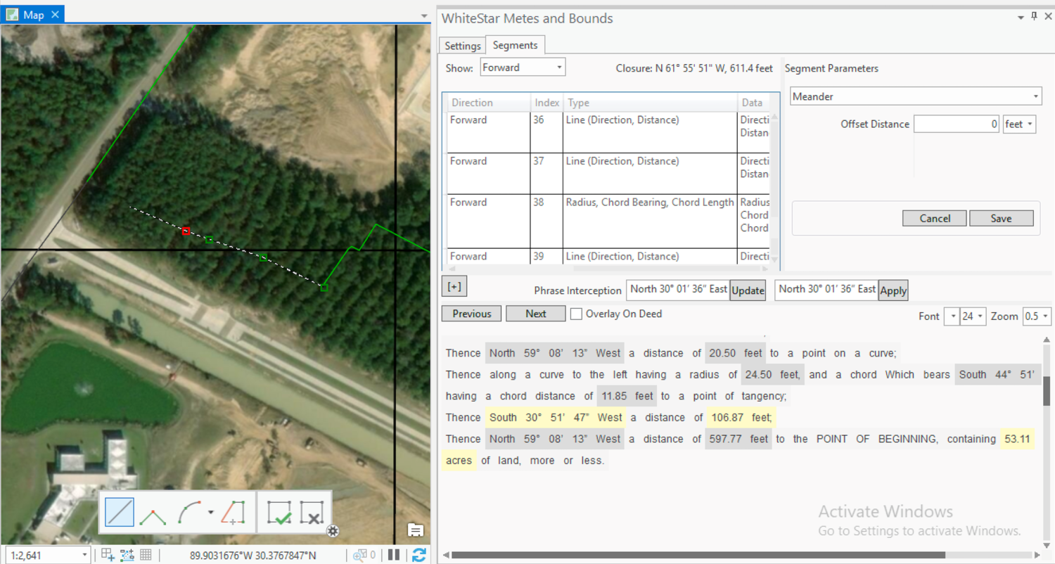
Segments panel
The segments panel contains all the controls used to extract, view, and edit segments and the corresponding parameters from a deed.
Direction filter combo box
Sets the filter for viewing deed segments in the grid view below. Commencement, forward, and back modes allow adding new segments, ‘All’ allows editing existing segments.
Segments grid view
Displays the parameters and metadata for each segment. Click on a segment to highlight the parameters in the deed and also the line segment(s) in the map view.
Closure indicator
The closure indicator displays the forward line segment that would close the polygon. You can double-click on the closure indicator to add the closure segment to the forward path.

Add a segment
Add a segment by right-clicking a segment row in the segments data grid. You’ll be prompted to add a segment before or after the selected one, or to edit or delete it.

Shortcuts
Click the [+] button or below the segments data grid to append a new segment to the plat. Or use the Control-A keyboard shortcut.

Parameter Sources and Overrides
The Add-In tracks the origin of each parameter and the history of any edits to it. For example, a line that was extracted from a deed may have had it’s parameter values edited from the deed if a number e.g. 17 feet was misinterpreted by the OCR engine as 11 feet. In this case, the modified value would be used and the parameter override would be included as metadata, showing the original values from the deed and the modified value. Similarly, if the line adjust tool was used, the original parameter values for direction and distance would be captured in the overrides column.

Re-ordering Segments
Right click on a segment to change its order (Move Up/Down) in the plat, or to relocate it (Move to...) to commencement, forward, or backward.
Deed viewer
The deed viewer occupies the bottom part of the dock panel. It shows the text extracted from the deed or, optionally, highlights the phrases extracted from the deed overlaid over it. In either mode, selectable, available, and used parameters are highlighted (default is light yellow for current/available and grey for used). Deed highlight colors can be set in color/line settings.
Deed viewer settings
The menu at the top of the deed viewer panel contains buttons to navigate to the previous and next page of the deed, a checkbox to switch between text and overlay modes, and controls for adjusting the font, font size and zoom level.
Text mode
In text mode, words in the deed are wrapped in the viewer and whitespace is only displayed between sections.
Overlay mode
In overlay mode, the original deed image is highlighted. By default, highlights are rectangular, semi-transparent blocks but text and switched on/off and opacity can be changed from 1-100% in settings.
Selecting a parameter
Click on a parameter in the deed to add it to a segment currently being added or edited. This will populate the first parameter of its type (i.e. distance or direction) in the segment editor. If multiple parameters of the same type define the curve type, click the input box for subsequent parameters to populate them.
Phrase interception and editing
When you click on a highlighted phrase in the deed viewer, the phrase interception control will display above the deed viewer. The parameter value will populate the segment parameter with the value if it is immediately recognized. If there is a problem with how the text was interpreted, you can edit the inbound text:

Deed viewer settings
The menu at the top of the deed viewer panel contains buttons to navigate to the previous and next page of the deed, a checkbox to switch between text and overlay modes, and controls for adjusting the font, font size and zoom level.
Text mode
In text mode, words in the deed are wrapped in the viewer and whitespace is only displayed between sections.
Click on the parameter in the deed
Edit the text for the parameter in the input box to the left
If the parameter is interpreted as valid, click Apply to push it to the segment parameter panel
Adding a missing parameter
You can manually input a parameter in any of the parameter value input boxes by typing it in to the input box. In this case, the parameter value is treated as an override.
Alternatively, you can select a rectangle around deed text in overlay mode and add the phrase to the set for the deed. Note, parameter interception works the same for phrases added manually.
Parameter units
Parameter units are displayed next to the parameter values for distance parameters. The add-in attempts to populate the units from the recognized text and parameter units can be changed and converted using the combo box to the right of the parameter input boxes.
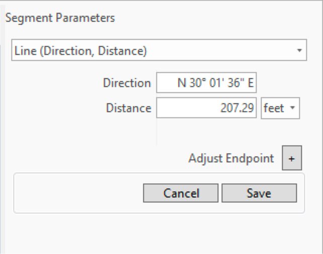
Segment parameter panel
Segment parameters are set and edited in the panel on the upper right. The segment panel has a combo box for setting the line or curve type, and input controls for setting and editing parameters.
Line adjust tool
Click on the end-point adjust tool then select a point on the map. Repeat as necessary. Changes are applied when the segment is saved.
Meander tool
Select the meander type in the segment parameter editor to enable the meander tool.
Trace mode
The meander tool traces geometry present in the active map (trace mode can be deactivated in settings).
Trace offset
The offset input box allows you to specify an offset distance. Positive offsets are outside concave and above or right of straight segments.
Utilities
Regular Expression Editor

Launch the regular expression editor from the Settings tab. It allows you to customize the regular expressions used to find segment parameters in the deed. It consists of three panels.
The upper-left panel contains a data grid showing the current set of regular expressions used by the project. Regular expressions are searched top-down on the list with priority given to the first result. The right-click context menu allows you to enable or disable regular expressions, create new ones from copies, delete or edit them. Edit enables the regular expressions editor in the upper-right panel.
In the edit panel, you can enable or disable the expression, change or set the parameter type and number of parameters searched. Type the regular expression in the Regular Expression text box. Optionally, enter an example or examples of the parameter in the Example box.
As you edit the regular expression, the words found will highlight under the example text box. If you enter an invalid regular expression, the text will turn red until the error is fixed and the regular expression tooltip will display a description of the error.
The bottom panel will show a preview of the active set of regular expressions overlayed on each deed in the project. When you are satisfied with your changes, hit the Apply to Project button in the upper-right corner of the editor. Use Restore Defaults to undo any changes you made to regular expressions.
